Geometric Dimensioning and Tolerancing (GD&T) is the language linking design, production and metrology. When it is misinterpreted, the result can be conflicting measurements, scrap and back-and-forth between teams. Metrologic DCS notes that Product Manufacturing Information (PMI) is increasingly embedded in CAD files and that standards continue to evolve, multiplying opportunities for error. The company has published four recommendations for making the path from design intent to shop-floor reporting reliable.
Start with PMI and preserve design intent
Metrologic DCS advises users to begin with the PMI and decode the design intent: which feature is targeted, which references apply and which tolerance is specified. Manual handling is prone to error, such as a copied value or a misunderstood reference, which can lead to inspection against the wrong requirement. The company recommends software that takes PMI as its starting point instead of requiring tolerances to be re-entered. Features and evaluations can then be created from the part’s digital definition, reducing re-keying and interpretation gaps while saving time in program preparation.
Automate datum reference frames
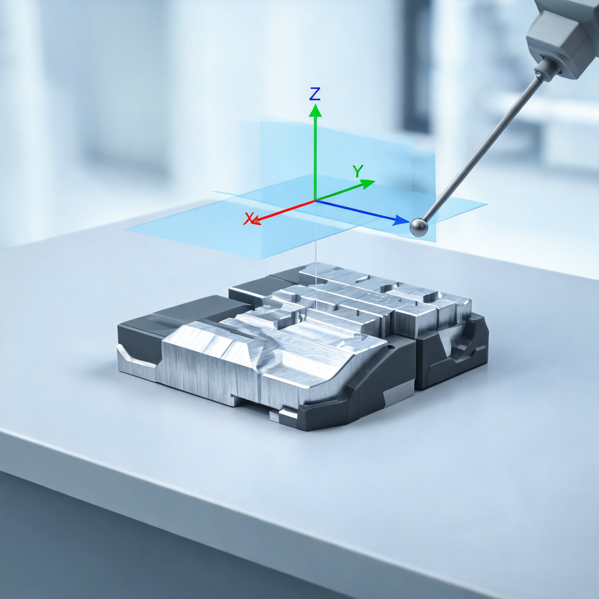
The Datum Reference Frame (DRF) defines where measurement begins. It consists of reference features A, B and C and determines which degrees of freedom are constrained. Metrologic DCS warns that building the DRF in the wrong order or selecting degrees of freedom poorly can lead the same part to be declared conforming or non-conforming depending on the operator. It recommends automating the step so the DRF and degrees of freedom follow the drawing definition. In Metrolog, the company says, the DRF is created automatically when a GD&T is evaluated and degrees of freedom are selected accordingly.
Reuse imported DRFs and tailor reports
References A, B and C are already defined in the CAD model, according to the company. Recreating them during program preparation wastes time, can introduce discrepancies and forces rework when definitions change. Metrologic DCS recommends starting from PMI-derived DRFs, predefining GD&T from them and tracking which annotations have been handled and which remain. In Metrolog, Scan GDT reads decoded PMI and assigns a status so users can validate decoding and measurement.
Reports limited to pass or fail do not tell the shop floor what to correct, the company argues. It recommends a numerical table for quality control, a Go/No-Go report for quick decisions and a decomposition analysis for the operator. Metrolog splits a feature defect into form, size, position and orientation, alongside the global defect, so the dominant type is visible. Metrologic DCS says a good report can reduce scrap and speed corrective action.